

Commodore’s Garage #9 – Bump Springs
September 30th, 2016 by Matt Holden
So far we’ve gone over how the main springs work on the car, but we still need to cover secondary springs, or “bump stops”. iRacing has recently overhauled the Gen 6 Cup cars and the Xfinity cars to use bump springs, but those still fall under the category of bump stops. To understand why the Gen 6 car was changed over to bump springs, we need to know the reason behind bump stops in the first place. As you can imagine, there’s a lot to go over.
Bump Stops
Bump stops have traditionally been used in motorsport to literally stop “bump” travel in suspension systems. Bump travel specifically refers to compression of the suspension…usually over a bump…or from aerodynamic loading, braking, and even acceleration. One of the earliest uses I know of is Williams F1 using bump stops to get around Formula 1’s 6 cm ride height rules, which were intended to reduce downforce levels from the evolving ground effect phenomenon. The cars ran softer main springs but eventually compressed into bump stops at full compression to keep the car off the ground under the high aerodynamic loading.
NASCAR teams did something similar when the COT was introduced in 2007. The bump stops that were allowed with the new car were used to prevent the car from hitting the track, while the springs used in the cars were huge by the day’s standard, a far cry from the “baby buggy” soft springs used in previous years. Larry McReynolds said during the spring Bristol practice in 2007 that the springs in the cars that were on track were of rates he hadn’t seen since the 90s. The cars “sucked” to drive, probably attributed to the horrible aerodynamic platform they had.
Bump Stop Rate
At some point (my guess would be lap 2 of that Bristol race) someone realized the rubber bump stops had their own spring rate, and they began using that as the at-speed spring rate for the front end of the car. If we fast-forward to 2012, bump stops had been engineered to be much more consistent, specifically in rate progression through travel. When coupled with the pig-tail spring assemblies, this could be used to keep the splitters sealed and the car handling relatively consistently through a race.
The issue lies in the behavior of spring rate in a rubber bump stop. While coil springs are engineered to produce a consistent rate through as much of the full travel range as possible, rubber material basically cannot do that if used in a solid shape. Instead of a constant rate, a rubber bumpstop will gain rate through compression, known as a progressive-rate spring. While a coil spring may produce forces of 250 lb at 1″, 500 lb at 2″, and 750 lb at 3″ (a 250 lb/in spring), a bumpstop could produce 100 lb of force at 0.1″ of compression, 250 lb at 0.2″, but 700 lb of force at 0.3″ of compression. An example graph is shown below. When compared to the conventional coil spring, a rubber bump stop could potentially increase the suspension’s overall rate by a lot in a very short amount of travel. In simplified terms when the above example is considered, we’re working with 1000 lb/in of rate at 0.1″ of compression, but we’re going to be over 2300 lb/in at only 0.3″ of compression! This sharp increase in rate would be immediately apparent to the driver, and could produce unpredictable handling swings if not controlled properly.

This is an example comparing a typical rubber bump stop rate (left, blue) chart with a spring rate (right, red) chart. Note how the bump stop graph gains a lot of force in a small amount of compression, eventually gaining a tremendous amount of force very quickly when compared to the spring’s linear force curve.
In the real world, rubber bump stops can be further complicated by the shape of the bump stop itself, the spacers in between the bump stops, and even how many make up the entire stack itself. Remember that springs in series wind up producing a lower rate than when used individually, and combine that with the exponential gain in force these can produce, and you can run into some major headaches! This led to the need for stiffer springs (for rate control) without super-stiff shocks, but there was still a need to circumvent the ride height rules, so we wind up with incredibly expensive pig-tail springs and bump stop-specific shocks. Below is a composite picture (credit: RE Suspension) of three types of bump stops that were common in oval-track racing. These are all shown with the shock compressed to the point of contact, but take note of the different style of washers in the middle, “puck”-style, bumpstop assembly. Each has a different angle on the cone-like face, which would change the way the bump stop generated force under compression!
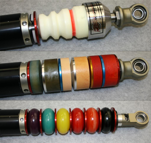
Some fairly typical rubber/composite bump stops seen in oval track racing. The top-most bump stop is typical for late model stock cars, sometimes called a “Christmas tree” bump stop. The middle set is known commonly as “puck”-style bump stops and the the bottom is a series of “roller skate wheel” bump stops. Each of the lower two shows the various sizes and stiffnesses (identified by color) available. (from RE Suspension)
The Bump Spring
Enter: The Bump Spring. These likely started out on the weekly late-model scene, but the rubber bump stop eventually got unseated by what’s now known as a “bump spring”. The bump spring is very simple to understand, and works exactly like a typical main spring would, however it’s located on the base of the shock shaft where the bump stop would be located. Using a coil spring instead of a rubber bump stop effectively eliminates the exponential force increase present in the rubber bump stops, meaning the handling can be more consistent across unexpected conditions like bumps, aerodynamic issues (trailing behind another car) and even banking changes at a track like Homestead or Iowa. As you can see from the Eibach spring pictured to the left, it looks just like a normal spring, so there’s no witchcraft or confusing magic going on with how it works.
The mechanics of its operation are also quite simple, and mirror the bump stop in its operation. Whenever the bump spring contacts the shock body, this point is set specifically with “packers” (more below), the bump spring rate is then included in the overall spring rate of the suspension. If you think back a few weeks, I described how multiple springs in a given system will combine for a new rate. In this case again, we have a parallel spring system once the bump spring is active, so the bump spring rate adds to the main spring rate to provide an “active” spring rate. For instance, if I have a 500 lb/in main spring, the suspension is acting on 500 lb/in until the bumpstop is in contact with the shock, which I set at 2500 lb/in for this example. Once the bumpstop is in contact, I now have a suspension system that is behaving with 3000 lb/in through travel. Of course, the actual rate would be lower than this due to motion ratios between the main spring and the shock, as well as ratios between the wheel and spring locations. This can be disregarded though, because all of these ratios are constant across all of our cars.
It’s use, in iRacing’s garage, differs based on the car it is being used on. Currently, only the Gen 6 “Cup” car and the “Xfinity” Class B cars have bump springs and while the Xfinity car basically presents only one type of use, the Cup car can utilize the bump spring in many different ways. The Cup car is basically infinite in its possibilities. You can choose soft main springs and stiffer bump springs, you can run stiffer main springs and soft bump springs. You can run one, you can run both, or you can run no bump springs, there’s literally any configuration that you can make work. The main decision is based on the driver, and what they are looking for. I’ve worked with drivers who liked stiffer main springs with softer bump springs, but there were other drivers who hated the feel of the big main springs and refused to race that way. In 2015, when Gale Force Racing had almost seven cars running in the DWC-level PEAK Antifreeze Series, it was not a surprise to see seven different front end styles on track at once, and they all wound up doing the same thing.
The Xfinity Class B car, however, is fairly simple since it still runs with the minimum garage heights. For most tracks, you can run a soft main spring (careful to avoid binding if you go this route!) and then choose bump springs to ride on when you’re up to speed. Since the bump spring will activate at a lower ride height (and cannot be preloaded), it’s not uncommon to need a much stiffer bump spring than you’d normally choose as a main spring when starting at a high ride height. For instance, if we start the left-front corner at 5.5″ (minimum height) and we’ll hit the splitter on the track at 2.5″ of height, we have 3″ of height to take up. For the sake of examples, we’ll say the motion ratio in the suspension is 1:1, so we have 3″ of suspension travel to gather up to get the splitter down. We’ll install a 1000 lb/in spring on that corner and compress it three inches to get the splitter down, so it’s exerting 3000 lbs of force at this point. Now, let’s install a bump spring and a softer main spring to drop the nose quicker, and this bumpstop engages with 1″ left in the total travel available. I’ll use a 400 lb/in main spring at this point, so at 3″ of travel it’s pushing 1200 lb of force. We’re 1800 lbs short of our goal here, but we know that the bump spring will compress 1″, so it’s very simple: We’d need an 1800 lb/in bump spring to achieve this. We’ve gone from a spring rate of 1000 lb/in with a single spring to 2200 lb/in with the bump spring, but wind up with the same force at the end. It’s not necessary to go through all these steps with bump springs, but it’s intended as a way to explain why a stiffer set of springs is often seen when the bump spring is added!
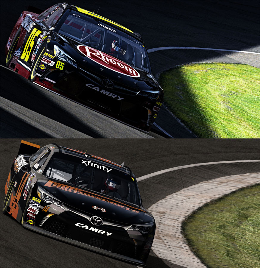
Above are the two cars Nick Ottinger and I used in our respective Indianapolis races this year. While both cars have a similar aerodynamic attitude on track, the bump spring arrangements were drastically different, despite producing nearly the same result.
Bumpstop Gap, Packers/Shims
Finally, we’re going to look at what’s used to tune the bumpstop contact point. The point where bump stops engage is crucial to how the car handles. In terms of driver feel, contacting a bump stop is basically the same as multiplying a given corner’s spring rate in an instant. It’s also possible to run into big swings in cross weight if the bump stops don’t engage properly, which can lead to major issues at tracks where the car “lands” heavily in the banking, such as Dover or Charlotte. Our tuning tool for this is the packer, basically a small shim that sits on top of the bumpstop stack to manipulate when the bumpstop engages in the suspension. Below is another picture from RE Suspension of their metal-dish bellows bump stop (very common in late models and possibly even Cup) that has a similar spring rate behavior as the coil bump spring:
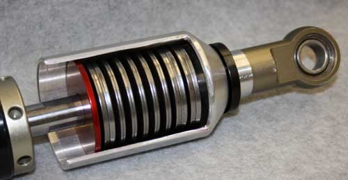
The metal dish “bellows” style bump stop has become increasingly common, offering a wide range of rate options with the benefit of a linear rate through travel. (from RE Suspension)
What we’re looking at is the actual bumpstop stack at the bottom of the shock. Here we have a lot of metal washers shaped like cones that are stacked in opposing directions, re-creating a bellows-style spring. The large part on the outside (with a cutaway) is the bumpstop cup, used to align all the components and keep them all compressing in a consistent manner time after time. Inside the cup are the metal washers, all stacked at the bottom of the cup. On top of the washers is a red washer, used to ensure the bump stop engages consistently across the entire surface of the bump stop. The very left of the image has the bottom of the shock body. The distance between the shock body and the red washer is known as the “bump stop gap”. The bumpstop will not be in play until the shock body contacts the red washer. We can add shims (which sit on top of the red washer) to reduce the bump stop gap, or remove them to increase the gap. In the image of the three bump stop styles, there are two packer shims installed at the top of the upper-most (white “Christmas tree” bumpstop) assembly. We’ll look at how to set the packers in a later article, but for right now, take the time to consider why having the bump stops engage at different points would produce an ill-handling or unpredictable car.
The bump stop trend is confusing, I’ll admit. There are a lot of things at play when they’re installed on a car, and the days of slapping them onto a shock simply to keep the car from bottoming out are gone completely. The learning curve is very steep, mainly because everything about them goes against traditional thinking, but once they’re understood it becomes fairly easy to manage what’s going on. It’s okay to get frustrated, that’s a given, but when that happens take a step back and try to envision what all is going on and what you can do to fix it. Working with two springs per corner is not easy, but everyone can do it, it just takes a bit of patience!
~~~~~~~~~~~~~~~~~~~~
Images in this article were sourced from RE Suspension in Mooresville, NC. For anyone who would like to see more images of various bump stop types and arrangements, as well as various rate and force graphs for a given type of bump stop, check out their website at http://www.resuspension.com
~~~~~~~~~~~~~~~~~~~~
To keep up to date with The Commodore’s Garage, return to Sim Racing News every Friday afternoon and “Like” our page at https://www.facebook.com/CommodoresGarage

You may also like...


OFFICIAL PARTNERS:


")

Customize Cookie Settings
Performance Cookies
These cookies gather data on how visitors use this website – which pages are visited most often, for example.
Functional Cookies
These cookies remember website preferences and generally improve the performance of the site for the user.
Marketing Cookies
These cookies are used to provide a customized experience and can be used to provide targeted ads through advertising networks.

Enhance Your Experience with Cookies
We use cookies to improve your site experience. Customize your cookie preferences below.
Copyright © 2024 iRacing.com Motorsport Simulations, LLC. All Rights Reserved.